
E3: Cavity QED on an Atom Chip

Lab room: B167 Birge
Lab phone: (510) 643-8152
Researchers: Julian Wolf, Josh Isaacs, Olive Eilbott, Kevin Mours
Prospective students: Scroll to the bottom of this page for a virtual tour!
By integrating trapped ensembles of ultracold atoms and high-finesse cavities with an atom chip we are able to study and control the classical and quantum interactions between photons and the internal/external degrees of freedom of the atom ensemble.
For more details, see Research Highlights.
Using copper wires embedded in an atom chip, we magnetically trap and transport an ensemble of ultracold Rb-87 atoms into a high-finesse optical cavity. We then transfer the ensemble into a single node of a standing-wave optical dipole trap, resonant with a very far-detuned longitudinal mode of the cavity.
A 780nm probe laser, resonant with another longitudinal cavity mode and detuned from the atomic D2 transition, dispersively interacts with the atomic ensemble. The coupling of the atomic ensemble to the standing-wave probe intensity is position- and spin-dependent. Probe light transmitted through the cavity mirrors therefore carries information about the collective position and spin of the ensemble, which is recorded using an optical heterodyne receiver.

Cross-Section of chip and cavity. Cavity mirrors are separated by 250 μm
Schematic of an atom chip on a silicon substrate incorporating a Fabry–Perot cavity. A hole is micromachined in the substrate to allow light occupying the cavity mode to pass through.
The interaction of the probe with the spin of the atomic ensemble results in scalar and vector Stark shifts of the atomic states, along with a dispersive cavity shift proportional to the total atomic spin component along the cavity axis. The vector component of the Stark shift acts as an effective magnetic field along the cavity axis, and the dispersive shift facilitates measurement of one component of the total atomic spin.
Conceptual diagram of a spin oscillator interacting with the probe laser.
For small excitations, a spin-polarized atomic ensemble precessing around a magnetic field transverse to the cavity axis can be described like a simple harmonic oscillator. The component of the total spin along the cavity axis is measured by the probe, resulting in measurement back-action in the orthogonal component, required in order to satisfy the spin uncertainty relation. Considering these the position and momentum of a harmonic oscillator, respectively, this is directly analogous to cavity optomechanics, immediately yielding many similar results as developed in our previous theory paper.
Recent E3 experiments have focused on realizing these spin-optodynamics analogues of optomechanics, as well as exploring some of the unique features a spin oscillator presents, such as a widely tunable Larmor frequency, a zero-temperature thermal bath, and a negative temperature, high-energy 'ground state'.
Applying a large magnetic field gradient along the cavity axis, we can spatially address spins in different lattice sites using radio-frequency (RF) radiation.
By chirping the applied RF, we flip the spins in each lattice site via rapid adiabatic passage. Each flip causes a step in the cavity shift. By taking the derivative of the cavity shift vs. time, we obtain a spatial image of the atom density along the cavity axis.
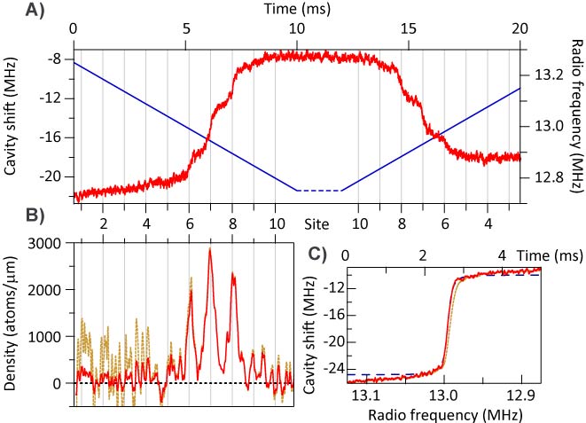
(A) Cavity shift as a function of time as RF is swept across the magnetic resonances of atoms in neighboring lattice sites. (B) Atom density in the lattice, as extracted from the cavity shift profile. (C) Rapid adiabatic passage with no magnetic-field gradient, showing a 14 kHz Rabi frequency. This is much less than the 50 kHz resonance splitting between adjacent wells, giving us 120 nm spatial imaging resolution.

Top: Schematic of atom-probe coupling for different well locations. Atoms (grey points) sit at the bottom of the FORT potential (black dashed line). Since the FORT wavelength is incommensurate with that of the probe, different wells lead to different levels of coupling (green dots on blue curve). Bottom: Experimentally obtained contrast plot highlighting the atom-probe coupling dependence on the location of the atom cloud.
Our experimental setup, based on a micromachined atom chip, allows us to freely position the atoms relative to the standing-wave probe. This allows us to access both linear and quadratic optomechanical coupling, dependent on the location of the atoms in the probe field. The strength of this coupling, along with the mechanical resonator frequency, can be tuned by varying the intracavity probe field intensity and its detuning from atomic resonance.

Top: Schematic of a piece of glass inside a cavity leading to a phase shift of the cavity light. Bottom: In our experiments, the trapped ensemble provides the phase shift.
Optomechanical resonators generally consist of solid-state devices. Our atom-based resonator does not suffer from many of the drawbacks found in typical solid-state systems, such as significant environmental couplings, thermal occupation of the mechanical resonator mode, and optomechanical parameters fixed during device fabrication.
The atomic ensemble behaves similarly to a dispersive piece of glass, changing the effective length of the cavity.

Atoms trapped in optical superlattice modulate the probe at distinct frequencies.
Statistical ensemble of measured states for oscillator 1 (top) and 2 (bottom), without (left) and with (right) coupling and the resulting backction.
With two optical dipole traps of incommensurate wavelengths, we create an array of loading sites with differing mechanical resonance frequencies, allowing us to separate spectrally the responses of atomic motion from neighboring sites.
This mechanical resonance separation technique has allowed us to apply and measure forces with unprecedented sensitivity and to couple mechanical oscillators together via the cavity probe field. For the latter experiment, we can observe the state of each oscillator evolve with or without coupling. Because the photonic coupling field can be measured as it exits the cavity, this kind of coupling necessarily introduces measurement backaction. In order to measure both the coupling-induced energy transfer and the coincident backaction, we acquire a statistical ensemble of many realizations of the coupling measurement.
The collective motion of the atoms' center of mass can act to suppress quantum noise fluctuations of the probe light. This suppression is called ponderomotive squeezing.
When the main source of noise on our probe light is photon shot noise, the optomechanical system is dominantly driven by these quantum fluctuations in radiation pressure. In such a system, by detuning our probe light from cavity resonance we close the gain loop and allow the optomechanical response to interfere constructively and destructively with input optical fluctuations, leading to spectral windows of amplification and of sub-shot-noise squeezing.

Power spectral densities of optomechanical response on a full scale (A) and magnified about the region of shot noise (B), in the phase-modulation (PM; red) and amplitude-modulation (AM; blue) quadratures (solid, data; dashed, theory).